Why this chapter exists
The right tools reduce rework. A cheap cutter that nicks conductors or a blunt punch blade can create intermittent faults that cost far more than the tool.
See the physical work before reading the details
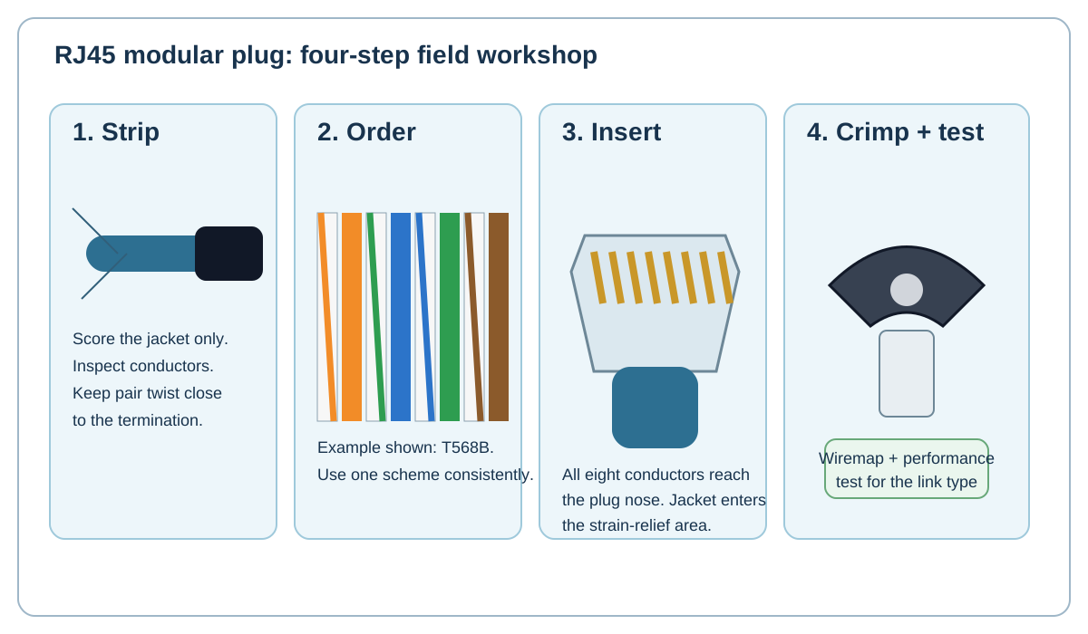
Original Netcomtech training illustration. Product-specific termination geometry varies, so use the component manufacturer's instruction sheet on site.
1.1 Tool groups and what each one proves
Separate tools into preparation, installation, termination, testing and documentation. A tool that makes a connection does not prove the connection performs to category.
Copper termination commonly needs cutters, a jacket stripper, manufacturer-approved termination tool or punch tool, and the correct modular-plug crimper if plugs are being installed.
1.2 Copper field kit
Include flush cutters, hook-and-loop, tape measure, marker, inspection light, label printer, spare jack/plug samples, punch tool with the correct blade, cable stripper and tester.
Avoid using a utility knife as the normal jacket-stripping method. It is too easy to score insulation or copper.
1.3 Pulling and pathway tools
Fish tape, pull rods, pull string, reel stands, cable carts, rollers and approved pulling lubricant may be required. Choose the method from the pathway and manufacturer limits.
A cable reel should pay out smoothly without twisting or dragging the jacket over sharp edges.
1.4 Fibre bench
Fibre requires dedicated stripping, cleaning, cleaving and inspection tools. Fusion splicing adds the splicer, cleaver, splice sleeves and preparation tools.
Use a controlled work surface and a dedicated container for bare glass shards.
1.5 Tester hierarchy
A simple wiremap tester proves basic conductor mapping. A qualification tester estimates whether an application may run. A certification tester measures the installed link against a standards limit. These are different jobs.
Choose the tool based on the acceptance requirement, not on which tester happens to be available.
Workshop exercise
Build a sample of this installation method on a training bench. Photograph the preparation before termination, the finished termination and the test result. Explain what would cause you to reject your own work.
Acceptance checklist
- The component matches the cable construction and category.
- The manufacturer's installation method was followed.
- No conductor, jacket, screen or fibre damage is visible.
- Pair twist, bend radius and strain relief are preserved.
- The correct test model and limit were used.
- The cable ID matches the drawing and test report.
Technical references
Manufacturer instructions and the project standard always override generic training examples.