Why this chapter exists
Higher-power cameras, access points and devices can increase bundle temperature and expose weak terminations that ordinary data-only links tolerated.
See the physical work before reading the details
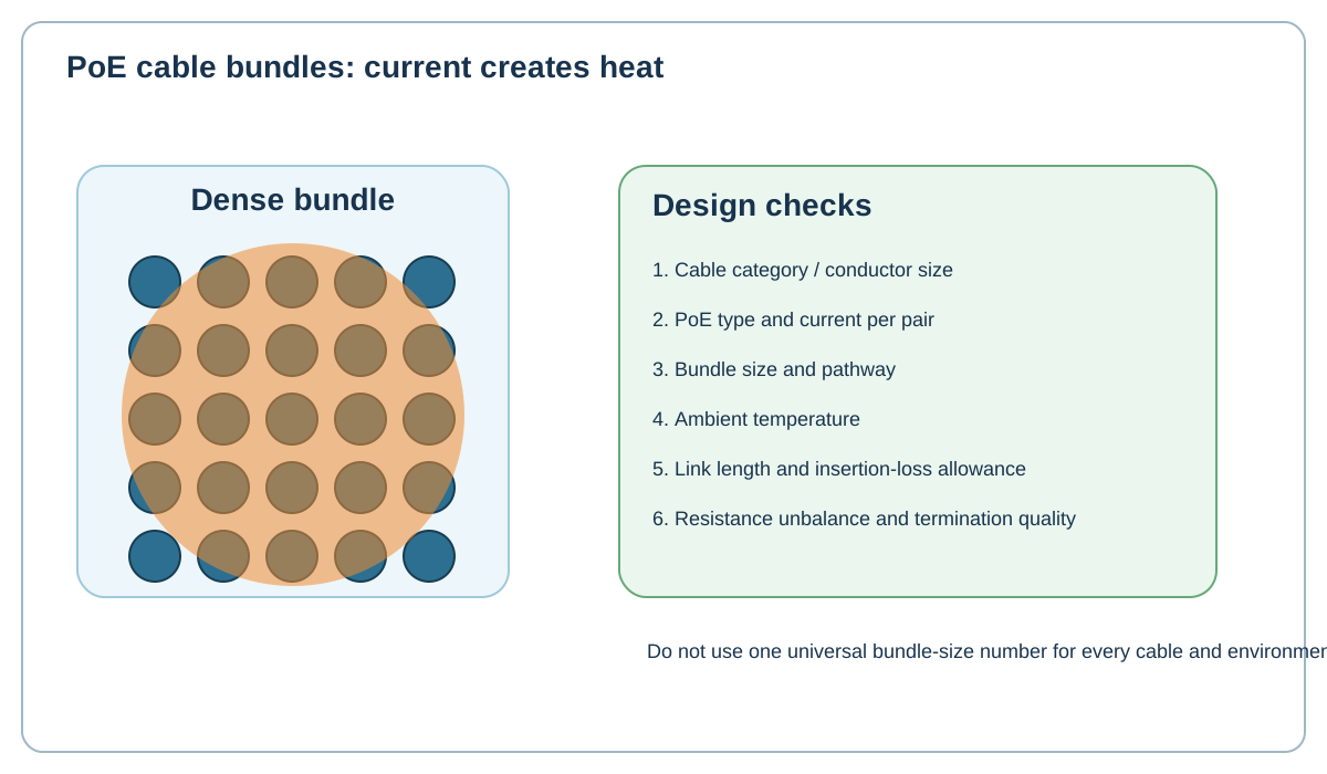
Original Netcomtech training illustration. Product-specific termination geometry varies, so use the component manufacturer's instruction sheet on site.
12.1 Current creates heat in conductors
Bundle temperature rise depends on current, conductor resistance, cable construction, bundle size, pathway and ambient temperature. Do not use one universal maximum bundle size.
CommScope notes a 24-cable bundle as a common recommendation from remote-powering guidance, but it is a recommendation, not a universal hard limit.
12.2 Category and conductor size matter
Larger conductors generally have lower resistance and less heating for the same current. Cat 6A commonly provides better thermal behavior than smaller-conductor constructions, but use the actual cable data.
12.3 Pathway matters
A bundle in free air sheds heat differently from a bundle in conduit or insulated spaces. Ambient temperature in ceiling spaces can already be high before PoE load is added.
12.4 Resistance unbalance matters
PoE relies on balanced current paths. Poor contacts or conductor resistance differences can create unbalance and heating. Modern certification options can include DC resistance and pair-to-pair resistance unbalance.
12.5 Design from the powered device population
Count the likely PoE class and peak load of cameras, APs, phones and future devices. Combine switch power budget planning with cable thermal planning.
Workshop exercise
Build a sample of this installation method on a training bench. Photograph the preparation before termination, the finished termination and the test result. Explain what would cause you to reject your own work.
Acceptance checklist
- The component matches the cable construction and category.
- The manufacturer's installation method was followed.
- No conductor, jacket, screen or fibre damage is visible.
- Pair twist, bend radius and strain relief are preserved.
- The correct test model and limit were used.
- The cable ID matches the drawing and test report.
Technical references
Manufacturer instructions and the project standard always override generic training examples.