Why this chapter exists
Split-pair faults can be difficult because a cheap continuity tester may show all pins connected while Ethernet performance is poor.
See the physical work before reading the details
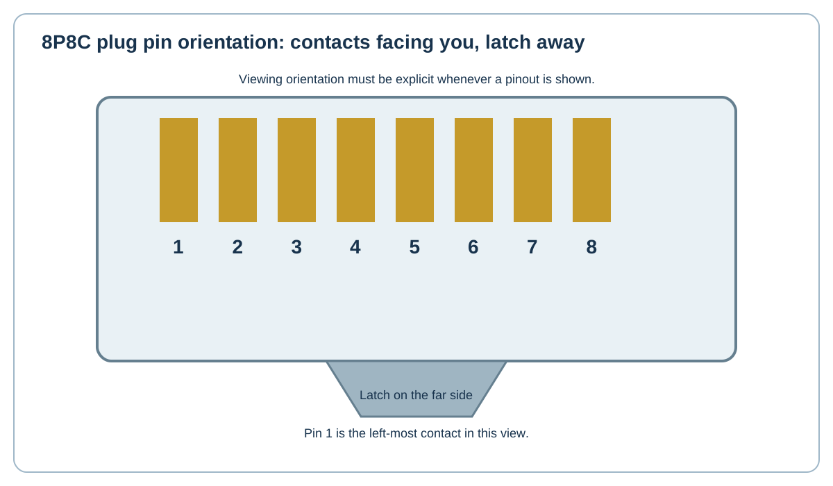
Original Netcomtech training illustration. Product-specific termination geometry varies, so use the component manufacturer's instruction sheet on site.
6.1 The four balanced pairs matter more than eight individual colors
Balanced transmission depends on conductors travelling as twisted pairs. A split pair puts the right pin numbers on conductors from different physical pairs and destroys the intended noise cancellation.
6.2 T568A and T568B are pair assignments
Both schemes keep the blue pair on pins 4-5 and brown pair on 7-8 while swapping the orange and green pair positions used on 1-2 and 3-6.
Straight-through links use the same scheme at both ends. Modern Ethernet equipment commonly supports auto MDI-X, so deliberately creating crossover patch cords is now far less common than in older books.
6.3 Always state viewing orientation
Pinout drawings must say which side of the plug or jack is being viewed. The Netcomtech drawing uses contacts facing the viewer with the latch on the far side.
For jack terminations, follow the connector's printed A/B legend rather than trying to translate a plug picture mentally.
6.4 Test for split pairs
Use a tester that can identify split-pair or certification faults. Continuity alone is not enough.
Workshop exercise
Build a sample of this installation method on a training bench. Photograph the preparation before termination, the finished termination and the test result. Explain what would cause you to reject your own work.
Acceptance checklist
- The component matches the cable construction and category.
- The manufacturer's installation method was followed.
- No conductor, jacket, screen or fibre damage is visible.
- Pair twist, bend radius and strain relief are preserved.
- The correct test model and limit were used.
- The cable ID matches the drawing and test report.
Technical references
Manufacturer instructions and the project standard always override generic training examples.