Why this chapter exists
Understanding the failed parameter helps a technician repair the right end of the link instead of reterminating everything blindly.
See the physical work before reading the details
Original Netcomtech training illustration. Product-specific termination geometry varies, so use the component manufacturer's instruction sheet on site.
15.1 Choose the correct test model
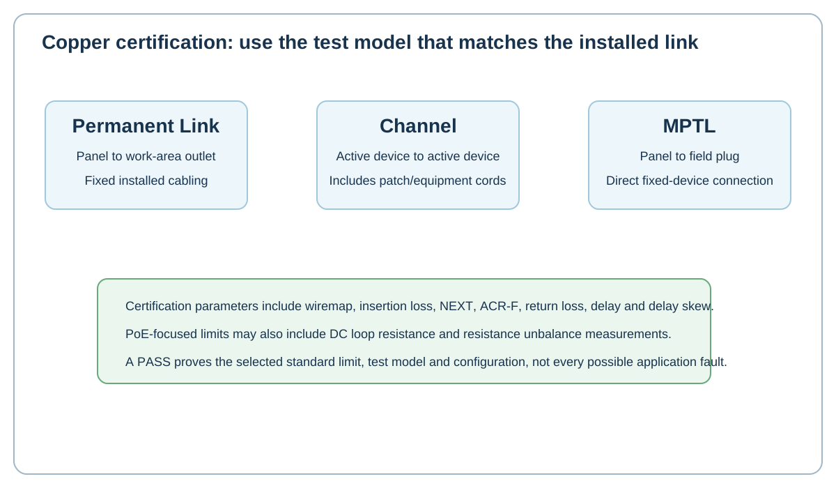
Permanent Link, Channel, Patch Cord and MPTL include different connection boundaries. Select the model that matches the installed system and customer specification.
For MPTL, use the correct adapters so the field plug is included.
15.2 Wiremap and length
Wiremap finds opens, shorts, reversals, crossed pairs and split-pair conditions depending on tester capability. Length/NVP measurements help identify unexpected cable length and locate some faults.
15.3 Insertion loss
Insertion loss is signal attenuation through the link. It increases with frequency, length and temperature. Excessive length, wrong cable or poor connections can contribute.
15.4 NEXT and ACR-F
NEXT describes near-end crosstalk between pairs. Poor termination geometry and excessive untwist are common suspects. ACR-F relates far-end crosstalk to attenuation.
15.5 Return loss
Return loss is affected by impedance discontinuities. Kinks, cable damage, water ingress and bad connectors can create reflections.
15.6 Delay and skew
Propagation delay is travel time. Delay skew is the difference between pairs. Extreme skew can affect applications that rely on all pairs arriving within allowed timing.
15.7 PoE measurements
Projects supporting remote power may require loop resistance and resistance-unbalance measurements in addition to normal category certification.
15.8 Keep native results
Export human-readable reports, but also retain the tester's native project files where possible. Native data often provides diagnostic plots that PDFs omit.
Workshop exercise
Build a sample of this installation method on a training bench. Photograph the preparation before termination, the finished termination and the test result. Explain what would cause you to reject your own work.
Acceptance checklist
- The component matches the cable construction and category.
- The manufacturer's installation method was followed.
- No conductor, jacket, screen or fibre damage is visible.
- Pair twist, bend radius and strain relief are preserved.
- The correct test model and limit were used.
- The cable ID matches the drawing and test report.
Technical references
Manufacturer instructions and the project standard always override generic training examples.